Rendering Model (proposed)
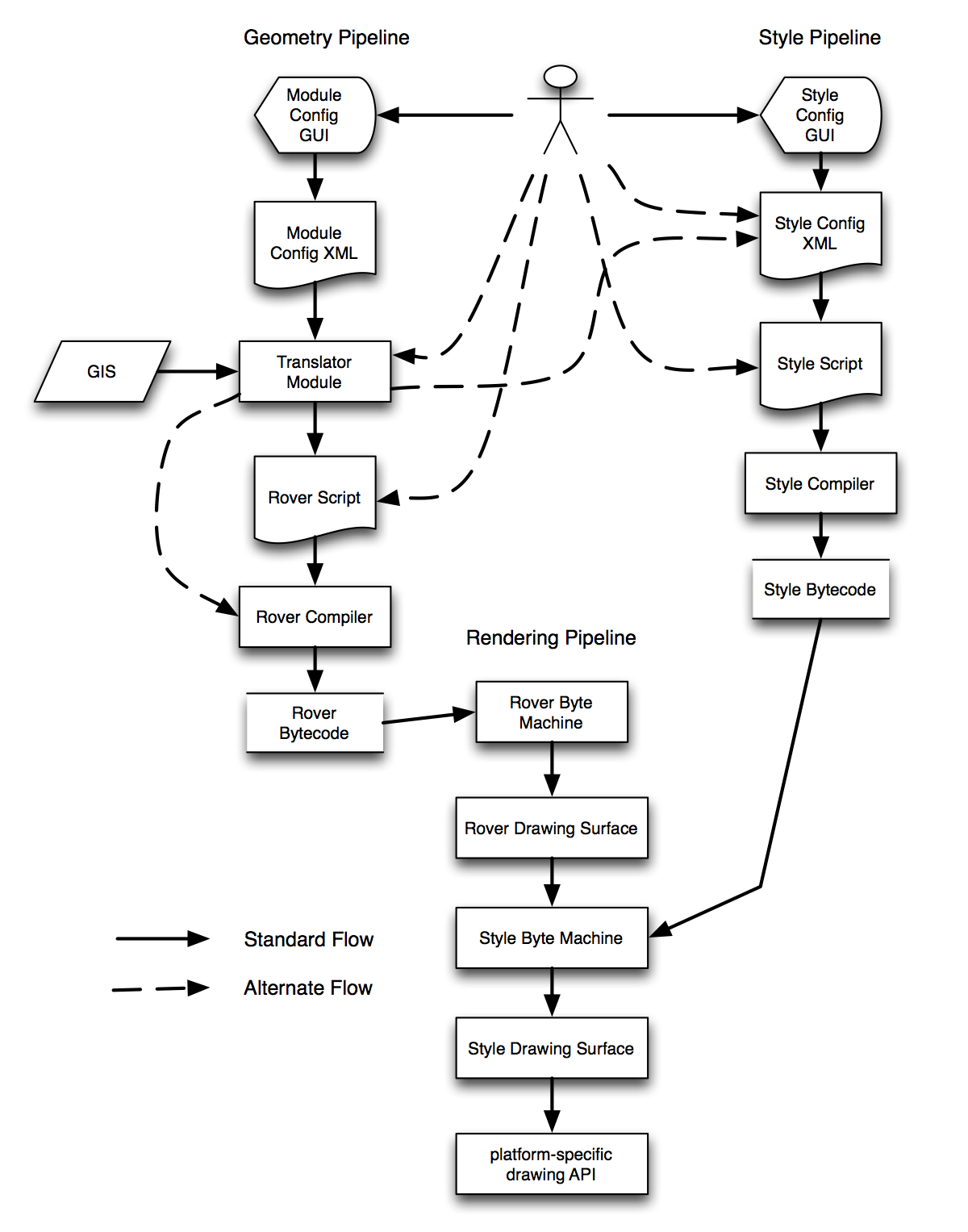
See the diagram below. It attempts to capture how data and configuration flow from various sources and formats, through various stages, to the final product of a rendered image on screen.
This follows a model very similar to that of compiled software. Actual running software is generally represented in a machine-specific bytecode, what’s usually referred to as “machine language”. The machine’s processor reads and executes this code directly. Since the bytecode is binary, low-level, and difficult to write and maintain, higher-level languages are provided. Generally there is an assembly language, that’s text but still low-level; something like C, that’s higher-level but still somewhat tedious; then there might be other languages that translate into C. So consider a scripting language that translates to C, that a compiler then translates to assembly language, than an assembler translates to machine language. A user might use a graphical IDE to edit the scripting language.
In our rover model, similar concepts would be: * a configuration GUI - the workbench and its forms; * a configuration language - generally COG XML; * rover script - does not exist yet; * rover byte code building API - DynamicMapTranslator and the translation engine; * rover byte code
Also consider that in our programming language example, a user might choose to program in the graphical IDE, or write the scripting language in a text editor, or skip the scripting language entirely and write in C, or in assembler, or even in bytecode.
Similarly, a user may use the Workbench forms gui, or edit the XML configuration directly (sometimes useful), or skip both and write in compilable rover script, program the building API directory, or even hand-hack rover bytes if desired.
Having full visibility of each of these phases is very useful for troubleshooting. In some cases (e.g. translating to rover script first, then compiling via the builder API) it might be less efficient; if so we could short-circuit by tying an input source directly to the API with custom translation code.
Having multiple options for representing this data is also useful; for example an optional flow shown is from the GIS, through the translation module, to style configuration. This represents the possibility of importing styles directly from a GIS rather than hand-configuring them. In some cases this may be useful to do on the fly; e.g. when you load an AutoCAD drawing the styles are embedded in that drawing rather than in a separate legend such as an ESRI system might provide.
In the diagram, there are two major publishing pipelines. The results of each are a bytecode format that is the primary input for the rendering pipeline.
The left pipeline is for geographic data. This pipeline doesn’t care about how things are drawn (styling), it only cares about the geographic shapes and associated data values in a map. This is similar to the approach in 4.4; the only addition is the concept of a compilable rover programming language.
The right pipeline is for style configuration. This pipeline doesn’t care about geography, but concerns itself, given some geographic shapes, with how they are drawn to the screen or page. The config GUI and XML formats exist in 4.4, but little else. The idea of a style language, compiler, and bytecode format are all new.
Given rover geography bytecodes produced by the left pipeline and style bytecodes produced by the right pipeline, the rendering engine combines them into a final rendering. Two machines are provided, one for each bytecode type.
The rover byte machine reads rover bytecode, does whatever transformation is required and fires commands at the rover drawing surface. Part of those commands are looking up styles for graphic types in the legend and switching styles (and therefore style bytecodes).
The style byte machine then processes the style bytecode, which uses geometry input and fires commands at the style drawing surface. The style drawing surface is probably pluggable with an implementation for each os- or purpose-specific drawing API such as OpenGL, Java2D, selection, or whatever. Note that, due to complex offset styles, style information is probably required even for data-oriented geographic queries or selection.
To summarize, here are the differences in this model from 4.4: * compilable programming language for geometry (rover) * compilable programming languages for styles * compiled bytecode format for styles * separation of drawing surfaces into a geometry-oriented surface and a style-oriented surface * explicit optional paths to write directly to lower-level stages (e.g. directly script a style rather than configure it)
And here are the advantages: * more possibilities for debugging and troubleshooting - e.g. looking at the rover script generated by a translator to see if there are errors in the translation logic * programmable styles - configuration driven styles are fine, but some may be simpler and easier to understand if programmed instead of configured * better separation of model (geometry) from presentation (legend and styles) * performance - bytecode format for styles should be more efficient and simpler than configured object model approach * portability - bytecode format for styles should be simpler to implement on a variety of architectures